 Datum Design Journal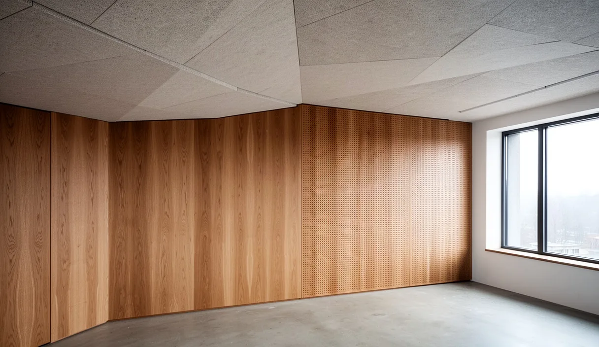
Acoustic treatment in commercial and institutional spaces requires balancing sound energy dissipation against interior architectural criteria. Acoustic plaster systems and perforated panel assemblies represent two distinct engineering methods for controlling reverberation time. An acoustic plaster system consists of a sound-absorbing substrate board, typically high-density mineral wool or expanded glass granulate, coated with an acoustically transparent, porous aggregate plaster finish. A perforated panel assembly relies on a rigid facing material, such as timber veneer, metal, or gypsum board, machined with round holes, slots, or micro-perforations, positioned over an air cavity containing an acoustic fleece and porous backing insulation.
Specifying between these systems dictates the mechanical attachment methods, plenum space demands, and life-cycle costs of an interior fit-out. Acoustic plaster provides a monolithic, jointless surface that functions through viscous friction in its interconnected microscopic pores. Perforated panels act primarily as resonant absorbers, functioning as collections of tuned Helmholtz resonators that target specific frequency bands. Selecting the correct assembly requires an analysis of sound absorption across discrete octave bands, tolerance for surface imperfections, and long-term facility maintenance protocols.
Noise Reduction Coefficient Metrics Across Frequencies
A single Noise Reduction Coefficient (NRC) or Sound Absorption Average (SAA) rating does not describe how a surface behaves across the full audible spectrum. Porous acoustic plaster surfaces typically provide broadband absorption that increases steadily from the lower mid-frequencies through the high frequencies. Sound waves enter the open pores of the aggregate finish and underlying mineral base, converting mechanical acoustic energy into low-level heat through boundary layer friction. Plaster systems with an overall thickness of 25 mm typically yield an NRC between 0.75 and 0.85, but their performance drops significantly below 500 Hz unless paired with a deep, insulated air cavity.
Perforated panels function as tuned resonators. Each perforation acts as the neck of an acoustic cavity, while the volume of air behind the panel provides the acoustic spring. This mechanical arrangement makes perforated panels effective for controlling low-to-mid-frequency energy, specifically the 250 Hz to 1000 Hz range critical for speech intelligibility. Changing the perforation percentage, hole diameter, panel thickness, and cavity depth shifts the peak absorption frequency. Micro-perforated panels, with hole diameters under 1.0 mm, introduce additional micro-turbulent friction, broadening the absorption curve without requiring a fibrous backing fleece.
| System Type and Configuration | 125 Hz | 250 Hz | 500 Hz | 1000 Hz | 2000 Hz | 4000 Hz | NRC |
|---|---|---|---|---|---|---|---|
| 25 mm Acoustic Plaster direct-fixed to concrete slab | 0.12 | 0.31 | 0.74 | 0.88 | 0.91 | 0.86 | 0.70 |
| 25 mm Plaster on 40 mm Mineral Wool with 100 mm Cavity | 0.43 | 0.72 | 0.93 | 0.87 | 0.89 | 0.84 | 0.85 |
| 12 mm Perforated Timber (16% open area) with 50 mm Cavity and Fleece | 0.28 | 0.64 | 0.86 | 0.73 | 0.54 | 0.42 | 0.70 |
| 12 mm Perforated Timber (8% open area) with 200 mm Cavity and 50 mm Insulation | 0.58 | 0.82 | 0.71 | 0.56 | 0.48 | 0.39 | 0.65 |
| Micro-perforated Steel Panel (1.5% open area) with 100 mm Air Cavity | 0.36 | 0.76 | 0.84 | 0.78 | 0.67 | 0.51 | 0.75 |
When an interior space exhibits low-frequency boominess, such as an auditorium or a conference room with large structural glass walls, perforated panels with an open area between 6% and 12% tuned to 250 Hz provide targeted remediation. Conversely, where speech privacy or general acoustic softness is required without directional frequency tuning, acoustic plaster yields higher performance across the 1000 Hz to 4000 Hz sibilance range.
Substrate Requirements and Cavity Depths
Acoustic plaster requires a rigid, unyielding substrate to prevent hairline cracking across its finished surface. Direct adhesive application requires a cured, flat concrete or masonry base that meets standard surface tolerance requirements (maximum 3 mm deviation over a 3-meter straight edge). If installed on a suspended metal framing grid, the framing members must be spaced at maximum 400 mm on center, using heavy-duty drywall furring channels. Framing must be engineered to a deflection limit of L/480 under dead load to prevent structural movement from translating through the plaster. The backing insulation boards, whether glass wool or expanded glass, are glued and mechanically fastened with counter-sunk acoustic washers. These washers must sit completely flush with the board face before the basecoat application.
Perforated panel systems impose higher demands on perimeter framing squareness but tolerate greater structural deflection behind the assembly. Panels are secured using split batten systems, heavy-duty Z-clips, or concealed torsion springs on heavy-duty ceiling grids. Framing for perforated panels typically allows a deflection limit of L/360. The primary design variable for perforated panels is the depth of the rear cavity. Because resonance frequency depends directly on cavity depth, reducing this plenum dimension alters acoustic absorption.
- Shallow Cavity Installations (40 mm to 60 mm): Suitable for acoustic plaster glued directly to a structural ceiling. Perforated panels installed at this depth will shift their peak absorption toward higher registers (800 Hz to 1200 Hz), requiring a higher open-area percentage to function properly.
- Medium Cavity Installations (100 mm to 150 mm): Allows both systems to operate efficiently across speech frequencies. This depth provides adequate space for a 50 mm layer of mineral wool insulation (density of 45 kg/m³ to 60 kg/m³) behind perforated panels, with an empty air gap completing the assembly.
- Deep Plenum Installations (200 mm to 600 mm or more): Perforated panels optimize low-frequency bass trapping in this range. For acoustic plaster, deep plenums require suspended drywall ceilings as substrates, adding dead weight that must be accounted for in structural load calculations.
Visual Continuity and Joint Tolerances
Acoustic plaster provides continuous plane surfaces. Installers bed reinforcing mesh across board joints using a basecoat aggregate, followed by one or two finish coats applied by spray and hand troweling. The final texture ranges from a fine granular surface, similar to a sandstone face, to a smooth, fine-grained finish. True Level 5 smoothness is not possible with acoustic plaster due to the microscopic void structure required for sound intake. The absence of visible expansion breaks is limited by thermal and structural movement. Unbroken runs of acoustic plaster require movement joints every 15 meters to 20 meters, or at maximum surface areas of roughly 150 square meters. Expansion joints must also mirror underlying building expansion lines.
Perforated panels treat joints as visible design elements. Variations in temperature and relative humidity cause timber and composite panels to expand and contract, requiring engineered reveal joints of 6 mm to 10 mm between adjacent panels. The visual field consists of a grid pattern, broken by these borders. Panel edges can be fabricated with square profiles, beveled profiles, or tongue-and-groove connections that conceal the fixings while preserving open slots.
Perforation design demands alignment discipline. If panels are slightly racked or the substructure is out of square by more than 1.5 mm over 2 meters, the horizontal and vertical lines of perforations will appear crooked under critical lighting. Acoustic plaster eliminates perforation alignment concerns but introduces side-lighting sensitivity: raking light highlights variations in hand-troweled aggregate. Specifiers must evaluate the building lighting conditions prior to selecting the final finish profile for acoustic plaster.
Long-Term Maintenance and Recoating Protocols
Maintenance procedures diverge between mechanical facings and porous finishes. Acoustic plaster absorbs dirt and airborne particles through passive room air circulation, an effect known as air filtration staining. Cleaning requires non-contact methods. Maintenance personnel must use vacuum cleaners fitted with soft brush attachments and HEPA filtration, held slightly off the surface to avoid burnishing the aggregate.
Water damage, grease, or severe impact requires localized patching for acoustic plaster. Standard drywall compound or joint filler cannot be used, as non-porous patching materials create an acoustically reflective spot that stands out visually. Repairs require proprietary repair mortars supplied by the plaster system manufacturer. Recoating entire ceilings presents the most significant operational hurdle. Standard latex, acrylic, or oil-based architectural paints completely seal the micro-pores, reducing the NRC of the assembly to 0.20 or lower. Recoating must be performed exclusively with manufacturer-approved, water-borne acoustic dispersion paints applied with a precise spray tip at specified wet-film thicknesses.
Perforated panels offer higher durability against mechanical abrasion, impact, and standard cleaning regimes. Metal and timber veneer panels with polyurethane or powder-coat finishes can be cleaned with damp microfiber cloths and neutral pH detergents. If an individual panel is damaged, it can be unclipped and replaced without affecting the adjacent ceiling or wall plane, provided that the manufacturer retains matching dye lots or grain selections.
- Plaster Recoating Threshold: Maximum of 3 to 4 maintenance spray coats over the life of the system before the micro-pores become bridged, requiring complete surface sanding or system replacement.
- Panel Impact Resistance: Perforated metal panels are rated for ball impact in sports facilities under DIN 18032-3; acoustic plaster requires protective high-impact base layers or must be kept above a 2.4-meter finished floor height.
- Dust Extraction: Perforated panels with an open backing require occasional vacuuming behind the face if used in return-air plenums where dust accumulates on the acoustic fleece.
Specification Checklist for Reverberation Targets
Executing an acoustic specification requires translating target reverberation times (RT60) into material schedules and contract documents. The following actions ensure proper coordination between acoustic targets and jobsite conditions.
Establish Target Reverberation Time
Calculate the required RT60 across octave bands from 125 Hz to 4000 Hz based on the room volume and primary use. Standard corporate conference rooms typically target an RT60 between 0.6 and 0.8 seconds; lecture halls require 0.7 to 1.0 seconds; public transit concourses and large atriums operate within 1.2 to 1.8 seconds. Use room modeling calculations rather than single-number average formulas.
Map Available Surface Areas
Identify boundaries suitable for treatment. If the ceiling contains extensive MEP services, recessed linear luminaires, sprinklers, and chilled beams, monolithic acoustic plaster becomes difficult to detail around penetrations. Perforated panels integrate cleanly with modular ceiling services because custom cutouts can be CNC-routed during factory fabrication.
Select Primary Material System
Specify acoustic plaster if the architectural program demands smooth, monolithic planes across curved or vaulted geometries. Specify perforated panels if target absorption must center on frequencies below 500 Hz, if the finish must resist heavy wear below standard wall-protection heights, or if continuous access to plenum-mounted mechanical equipment is necessary.
Define Plenum Depth and Infill Material
Document the exact cavity depth required in architectural sections. Specify backing insulation by thickness, density, and flow resistivity. For perforated panels, specify a non-woven, fire-retardant acoustic fleece factory-laminated to the rear of the panel face, supplemented with minimum 45 kg/m³ density bio-soluble mineral wool where lower-frequency absorption is needed.
Coordinate Jobsite Environmental Conditions
Acoustic plaster installations require strict environmental conditioning. The building envelope must be fully enclosed, with glazing installed and the HVAC system operational. Ambient temperatures must remain between 15 degrees Celsius and 30 degrees Celsius, with relative humidity held between 40% and 70% during application and for at least 10 days of curing time. Significant humidity swings during the drying phase cause discoloration and shrinkage cracks.
Common Mistakes
The most frequent failure in perforated panel specification is assuming that any perforation pattern will absorb sound. A panel with 2% open area functions as an acoustic reflector, not an absorber, regardless of the backing insulation. Minimum effective open area begins around 6% to 8%, while values between 15% and 22% provide optimal broadband performance. Another panel detailing error is failing to specify an acoustic fleece behind the panel holes, leaving the yellow or green mineral wool backing insulation visible from the finished floor.
With acoustic plaster, a frequent error is treating the system like conventional gypsum plasterboard. Painting crews unfamiliar with acoustic materials often apply standard commercial latex paint to cover minor scuffs or water stains, permanently compromising acoustic performance. A second error is installing acoustic plaster directly over green concrete slabs or unprimed drywall, which draws moisture out of the acoustic basecoat too quickly and leads to aggregate separation. Finally, failing to coordinate framing deflection tolerances results in ceiling cracks along structural framing junctions within the first year of building occupancy.
Practical Next Steps
To implement an acoustic solution using either material system, begin with an acoustic review of the space geometry. Engage an acoustic consultant during schematic design to run ray-tracing simulations and establish exact absorption coefficients per square meter. Request ASTM C423 or ISO 354 laboratory test reports from manufacturers, verifying that test mounting conditions match your project's proposed cavity depth and assembly details (for example, Type A direct mounting versus Type E-400 suspended mounting).
Before issuing final construction documents, detail all penetration profiles, perimeter shadow gaps, and access panels. Require the general contractor to construct a jobsite visual mockup of at least 4 square meters. This mockup must incorporate lighting that matches the final specified fixtures and lumen output, allowing all parties to review joint lines, edge trims, and surface textures under true project conditions.