 Datum Design Journal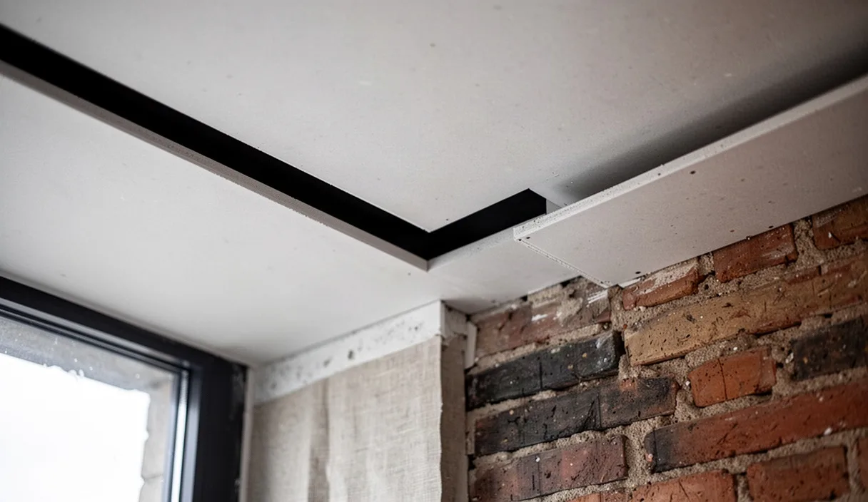
A shadow gap, also termed a reveal bead or perimeter reveal, creates a deliberate recess between the edge of a suspended drywall ceiling and an adjacent vertical surface. When the ceiling abuts masonry, such as poured-in-place concrete, load-bearing brick, or rough-faced stone, the intersection presents distinct mechanical and aesthetic challenges. Masonry substrates rarely present true plumb or planar planes. Simultaneously, suspended light-gauge steel framing shifts under live loads, thermal swings, and building settlement. Bridging this transition with traditional taped corner joints or rigid moldings invariably leads to stress concentration and perimeter fracture.
The shadow gap decouples the drywall ceiling from the structural masonry wall. By separating the planes by a controlled distance, typically between 1/2 inch and 1 inch, the visual line shifts from a flawed contact joint to an intentional negative space. This article documents the engineering principles, material selections, isolation strategies, and execution sequences required to build durable, fire-safe, and acoustically isolated shadow gaps between suspended drywall assemblies and masonry walls.
Structural Deflection Dynamics and Perimeter Cracking
Drywall ceiling planes hung from light-gauge cold-formed steel channels or timber joists move continuously over the building lifecycle. Floor joists and roof trusses above experience live-load deflection, calculated under structural codes as spans divided by factors such as L/240 or L/360. Under a live load of 40 pounds per square foot, a 20-foot mid-span joist can deflect downward by 0.67 inches. Masonry walls, conversely, exhibit high compressive stiffness with negligible vertical live-load deflection, though they remain subject to long-term foundation settlement and thermal expansion.
When ceiling drywall connects directly to perimeter masonry using standard corner beads and joint compound, the assembly forms a rigid triangle. As the overhead structure deflects, downward shear force transfers into the brittle gypsum board and joint tape. Because paper-faced drywall possesses low shear tolerance along its edges, the joint fails. The result is continuous spalling, edge crumbling, and horizontal hairline cracking along the wall-to-ceiling juncture. Thermal expansion differentials exacerbate the damage: gypsum expands at roughly 9.0 microinches per inch per degree Fahrenheit, whereas clay brick expands at 3.4 microinches per inch per degree Fahrenheit.
A shadow gap terminates the ceiling drywall short of the masonry face, eliminating mechanical bridging. The ceiling framing floats on perimeter tracks or hangs from spring-isolated suspension wires, allowing the horizontal drywall plane to deflect vertically without contacting the brick or concrete. For structural spans exceeding 30 feet, engineers design a minimum gap width of 3/4 inch to ensure that maximum downward and lateral drift values do not bring the drywall edge into contact with masonry high spots.
Aluminum Reveal Extrusions vs Vinyl Trim Profiles
Architectural shadow gaps rely on pre-formed termination trims fastened to the board edge. The two primary materials used for this application are extruded architectural aluminum alloy (typically 6063-T5) and rigid polyvinyl chloride (PVC). Selection depends on span straightness, substrate variance, moisture conditions, and budget constraints.
| Performance Metric | Architectural Aluminum (6063-T5) | Rigid PVC (Vinyl) Profiles |
|---|---|---|
| Flexural Rigidity | High; spans minor framing irregularities without dipping. | Low; mirrors deviations in drywall edges unless backed. |
| Thermal Expansion Rate | 13.0 microinches per inch per degree Fahrenheit. | 30.0 to 40.0 microinches per inch per degree Fahrenheit. |
| Impact and Edge Crispness | Produces sharp, defined 90-degree internal corners. | Slightly radiused corners; prone to burrs if cut cold. |
| Adaptability to Out-of-Plumb Walls | Requires precise shimming; cannot bend horizontally. | Flexible; conforms to gentle contours across broad masonry spans. |
| Corrosion Resistance | Requires chemical conversion or anodization in damp areas. | Inert; completely unaffected by damp masonry moisture. |
Extruded aluminum trims feature an integrated taping flange punched with knurled patterns to key into drywall compound. Because aluminum resists torsional twisting, it maintains an unwavering horizontal line across long visual corridors, such as commercial lobbies or gallery spaces. The material requires mechanical anchoring to the ceiling framing via self-drilling fine-thread screws spaced at 12 to 16 inches on center. If aluminum abuts damp masonry directly, galvanic and alkaline corrosion can degrade bare metal; installers must specify mill-finished aluminum coated with an etch primer or anodized to minimum Class II specifications.
Rigid vinyl profiles present a cost-effective alternative that works well in residential projects or residential units with short wall runs. Vinyl trims utilize perforated mud legs that accept staples or spray adhesives for temporary hold prior to mudding. While vinyl lacks the absolute structural rigidity of aluminum, its natural flex allows it to negotiate non-planar masonry substrates where an aluminum channel would bind or require excessive relief notching. Installers must account for higher thermal expansion rates by leaving 1/16-inch gaps between adjacent vinyl trim butt joints to avoid buckling during summer heat peaks.
Acoustic and Smoke Isolation Behind the Open Reveal
An open shadow gap creates an unsealed breach through the ceiling envelope into the interstitial plenum. Without corrective backing, this void degrades the Sound Transmission Class (STC) rating of the partition wall and voids smoke compartmentation requirements under building codes. Unmitigated gaps can drop a field-tested partition from STC 52 down to STC 33, allowing voice-range frequencies to flank across rooms over the top of the ceiling.
Acoustic and smoke containment behind a reveal requires three integrated components installed in the hidden cavity above the drywall line:
- Backer Track or Framing Ledger: A light-gauge steel runner channel (minimum 25-gauge) anchored to the ceiling framing or set off the masonry face to provide a rigid stop for drywall and firestop materials.
- High-Density Mineral Wool Insulation: Slags or rock wool safing insulation (density of 4.0 to 4.5 pounds per cubic foot) compressed a minimum of 25 percent into the perimeter cavity. The mineral wool dampens airborne sound and serves as a thermal barrier.
- Non-Hardening Acoustic Sealant or Intumescent Mastic: A continuous bead of non-drying synthetic rubber sealant applied between the back of the trim channel and the masonry wall. For fire-rated assemblies, installers apply a firestop sealant certified under ASTM E814 (UL 1479) or ASTM E1966 (UL 2079) for dynamic joints.
When fire ratings are mandatory, field crews cannot leave the internal reveal surface unshielded. The detail requires extending an internal leg of 5/8-inch Type X gypsum board vertically above the trim or lining the reveal cavity with fire-rated elastomeric compound. This elastomeric layer expands under heat to seal the shadow void against toxic fumes, smoke spread, and thermal transfer. Designers must verify the specific tested UL design number, as deviations in joint width or backing density void the system rating. Consult a licensed fire protection engineer or certified life-safety inspector to confirm dynamic movement allowances for the chosen assembly.
Scribing Techniques Against Irregular Masonry Bonds
Masonry walls built from historic common brick, rusticated ashlar, or split-face concrete masonry units (CMU) present irregular vertical planes that deviate by up to 3/4 inch over a 10-foot run. If an installer snaps a straight chalk line and sets a rigid shadow bead parallel to that line, the reveal width will fluctuate visibly from 1/4 inch to 1 inch along the span. Scribing the backing assembly or the drywall trim edge normalizes the perceived shadow line.
To establish a uniform reveal width against irregular masonry, implement the following scribing sequence:
- Survey the Masonry Plane: Stretch a taut nylon string line along the length of the masonry wall at the finished ceiling elevation. Measure the offset distance at each mortar joint and stone face to find the maximum outward projection (the high point) along the wall.
- Set the Control Line: Establish the primary ceiling line parallel to the building grid, offset from the masonry high point by the specified gap dimension plus the trim channel depth. For a 1/2-inch reveal trim, add 1/2 inch of clear air space, placing the line 1 inch outward from the masonry high point.
- Prepare a Backing Cleat: Install a continuous, light-gauge galvanized steel angle (such as 2-inch by 2-inch, 20-gauge) or an exterior-grade plywood ledger along the wall perimeter above the ceiling level. If the wall deviates drastically, mount the ledger to the overhead structure rather than anchoring into soft, historical mortar joints.
- Transfer the Profile with a Compass: Position a temporary piece of rigid backing or continuous drywall spacer board against the wall. Set a scriber or mechanical drafting compass to the exact dimension of the maximum cavity depth. Draw the compass downward or horizontally along the masonry face, transferring the stone or brick relief profile onto the board.
- Cut the Relief Line: Cut along the scribed pencil mark using an oscillating multi-tool fitted with a carbide grit blade for cementitious materials, or a jigsaw with a fine-toothed blade for board stock. Sand or rasp edges smooth to prevent snagging during dry fitting.
- Install the Shadow Profile: Fasten the shadow gap profile directly to the scribed ceiling framing edge, maintaining a constant recess distance from the scribed line. This ensures that the face flange of the trim remains planar and true to the ceiling, while the inner recess leg masks the natural variations of the masonry.
Sequence of Application for Taping, Mudding, and Painting
Finishing a shadow gap requires precise sequencing. Joint compound that spills into the reveal channel creates rough, shadowed lumps that defeat the purpose of the detail. Cleaning hardened compound out of a narrow 1/2-inch channel without gouging aluminum coatings or scratching vinyl requires destructive scraping. The application must follow strict protection and curing protocols.
Masking and Mechanical Attachment
Drywall ceiling boards must be fastened up to the perimeter reveal profile with drywall screws spaced 8 inches on center along the edge. The board edge must sit square against the trim seat without bowing the profile flange. Before applying any compound, install continuous low-tack protective tape directly into the bottom and back of the reveal channel. Most premium aluminum and vinyl reveal trims ship with removable protective plastic films on their exposed interior legs; confirm this factory masking remains fully adhered before proceeding.
Bedding Coat Application
Apply a setting-type chemical-cure joint compound (such as a 45-minute or 90-minute formulation) into the perforated mud leg of the trim. Chemical-setting compounds experience less shrinkage than air-drying compounds and form a high-strength mechanical bond with perforated metal or vinyl flanges. Embed a 2-inch wide strip of high-tensile fiberglass mesh tape or pre-creased paper drywall tape centered over the seam between the trim flange and the drywall board. Press the tape firmly with a 4-inch taping knife held at a 30-degree angle to purge air bubbles and excess mud, taking care not to bridge mud over the reveal opening.
Intermediate and Skim Coats
Allow the setting compound to fully harden. Apply a second coat using an all-purpose drying-type compound feathered outward 8 to 10 inches from the trim edge with a 8-inch finishing knife. Once dried, sand lightly with 150-grit sandpaper to eliminate ridges. Apply a final skim coat using a lightweight topping compound feathered out 12 to 14 inches from the trim using a 12-inch skimming blade. The objective is to achieve a flat Level 4 or Level 5 finish across the ceiling plane without creating a crown near the edge of the shadow bead.
Surface Preparation and Coating
Vacuum all dust from the ceiling plane and wipe down the masonry face with a damp sponge to remove loose debris. Apply a high-solids PVA (polyvinyl alcohol) drywall primer-sealer across the entire ceiling plane up to the outer corner of the trim profile. Paint the interior channel of the reveal in the specified color. Architectural specifications typically call for painting the interior channel flat black (light reflectance value below 5) to absorb interior ambient light and maximize visual depth, or the identical color as the ceiling field to make the shadow line appear soft and suspended. Use a 1-inch foam brush or detail sash brush to apply paint within the channel, immediately removing accidental drips on the masonry face with a damp microfiber cloth.
Common Mistakes
Failure rates in shadow gap joinery correlate directly with shortcuts taken during framing installation and joint finishing. Inspect assemblies for these recurring errors:
- Rigid Fastening to Both Planes: Driving screws through the drywall or trim directly into the masonry wall locks the ceiling to the vertical structure, eliminating structural decoupling and causing premature perimeter cracking.
- Omission of Channel Masking: Applying joint compound without protective masking tape leads to mortar clogging inside the reveal, which requires manual chisel removal that damages factory paint finishes.
- Inadequate Framing Support: Hanging the ceiling drywall with an unsupported cantilever exceeding 6 inches from the nearest ceiling joist causes the drywall edge to sag under its own weight, twisting the reveal profile out of horizontal alignment.
- Overlooking Masonry Moisture: Installing unprimed aluminum extrusions against damp, uncured concrete or salt-efflorescing masonry induces chemical oxidation, pitting the aluminum and staining adjacent paint.
- Using Air-Dry Compound for Embedment: Setting perforated metal flanges with standard air-dry all-purpose mud often results in shrinkage voids beneath the metal leg, producing edge blistering months after occupancy.
Practical Next Steps
Begin implementation by reviewing the structural framing drawings to calculate anticipated roof or floor live-load deflections for the specific building bay. Cross-reference this deflection number against the manufacturer data sheets for the chosen aluminum or vinyl reveal bead to confirm that the gap dimension accommodates full design movement without binding.
Next, build an on-site physical mock-up measuring a minimum of 4 feet in length at a representative section of the masonry wall. This mock-up tests the scribing accuracy, verifies acoustic and smoke backing procedures, and provides the painting subcontractor with a clear quality benchmark for edge clean-up and channel finish. Obtain formal approval from the architect or client on this physical benchmark before general drywall board hanging begins across the project site.