 Datum Design Journal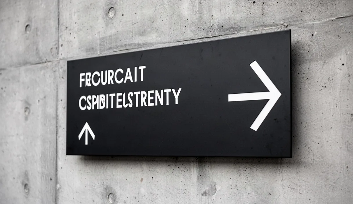
Wayfinding typography operates at the intersection of architectural circulation, visual optics, and regulatory compliance. Unlike editorial or screen typography, environmental lettering must perform under variable lighting, oblique approach angles, and rapid observer motion. The primary function of an architectural sign is to convey directional or locational data within the viewer visual window before that viewer passes the decision point or creates an obstruction in pedestrian flow.
Calculating the correct typographic scale requires measuring visual acuity, letterform geometry, and ambient luminance. Standard visual acuity metrics, such as the Snellen fraction of 20/20, assume a visual angle of five minutes of arc for the entire letter height, with one minute of arc per stroke width. In physical environments, however, visual degradation occurs due to atmospheric scattering, glare, sub-optimal sign positioning, and human visual impairments. Planning navigational panels requires explicit formulas that account for these physical parameters rather than relying on arbitrary aesthetic sizing.
Viewing Distance Equations for Primary Navigation Panels
Calculating the legibility of environmental lettering begins with establishing the relationship between the capital letter height (cap-height) and the maximum viewing distance. A standard baseline across spatial design is the legibility index, often expressed as a ratio of distance to character height. For individuals with baseline 20/20 vision under controlled lighting of 100 to 300 lux, a standard sans-serif letter remains legible at roughly 50 feet per inch of letter height (or 600 millimeters of distance per 1 millimeter of character height). However, wayfinding systems in public transportation, healthcare facilities, and educational institutions must account for observers with reduced visual acuity, typically calibrating to a 20/40 visual threshold.
To design for a 20/40 threshold, the legibility index drops to 30 feet per inch of cap-height (approximately 360 millimeters of distance per 1 millimeter of character height). When observers must identify text while walking at standard transit speeds (roughly 4 feet per second), the time required to detect, read, and interpret the sign requires adding a reading duration factor to the total distance. The primary equation for determining the minimum capital letter height on an approaching pedestrian path is expressed as follows:
H = (D / L) + (S × T × R)
In this equation, H is the cap-height in inches or millimeters; D is the target viewing distance at which identification must occur; L is the legibility factor (30 feet per inch or 360 millimeters per millimeter for 20/40 acuity); S is pedestrian travel speed in units per second; T is the detection and reading duration in seconds (typically calculated at 1.5 to 3.0 seconds for short messages of two to three words); and R is the optical scale correction factor for viewing angles that deviate from a perpendicular orientation.
| Viewing Distance | Standard Static Acuity (20/20) | Public Wayfinding Acuity (20/40) | Oblique Angle Approach (45 degrees) |
|---|---|---|---|
| 15 feet (4.57 m) | 0.30 in (7.6 mm) | 0.50 in (12.7 mm) | 0.71 in (18.0 mm) |
| 30 feet (9.14 m) | 0.60 in (15.2 mm) | 1.00 in (25.4 mm) | 1.41 in (35.8 mm) |
| 60 feet (18.28 m) | 1.20 in (30.5 mm) | 2.00 in (50.8 mm) | 2.83 in (71.9 mm) |
| 120 feet (36.57 m) | 2.40 in (61.0 mm) | 4.00 in (101.6 mm) | 5.66 in (143.8 mm) |
When an observer approaches a sign obliquely, foreshortening compresses the horizontal proportions of the letterforms. For an approach angle of 45 degrees, the projected character width is reduced by roughly 29 percent based on the cosine of the angle. To compensate without altering the typeface geometry on the panel, the designer must increase the overall cap-height using the optical scale correction factor, or reduce the maximum expected detection distance accordingly.
Stroke Contrast and Optical Spacing for Motion Legibility
Letterform geometry directly dictates whether a sign remains readable under motion blur or off-axis inspection. The two critical variables in typographic design for wayfinding are the stroke-to-height ratio and the horizontal tracking. Typefaces engineered for spatial navigation prioritize open interior counters, distinct character silhouettes, and balanced stroke weights that resist optical closing.
The optimal stroke-to-height ratio for positive-contrast signage (dark text applied to a light ground) falls between 1:5 and 1:7. A ratio heavier than 1:4 causes letterform interiors to fill in when viewed from beyond the baseline legibility threshold, particularly in characters like uppercase 'B', 'e', and '8'. Conversely, a ratio lighter than 1:10 causes the stroke to drop below the visual detection threshold before the overall letter boundary disappears.
Negative-contrast signage (light or illuminated text applied to a dark ground) behaves differently due to optical irradiation, also referred to as halation. Light strokes bleed into the surrounding dark field on the human retina, making the characters appear physically thicker than their true geometric dimensions. For internally illuminated panels or reflective white characters on dark backgrounds, the stroke-to-height ratio must be reduced to between 1:7 and 1:9 to counteract this optical expansion.
- Aperture size: Letterforms must feature wide apertures in glyphs such as 'c', 'e', and 's' to avoid confusion with closed shapes like 'o'.
- Terminals: Horizontal or vertical sheared terminals maintain clearer white spaces between strokes than rounded or angled calligraphic terminals.
- X-height proportion: An x-height measuring between 70 percent and 78 percent of the capital height optimizes legibility for mixed-case text strings.
- Letterspacing (tracking): Mechanical spacing suitable for print reading causes character collision at viewing distances exceeding 20 feet. Tracking must be loosened by 8 percent to 14 percent of the base em width to preserve the optical envelope of each glyph.
Luminance Contrast Requirements Between Sign and Substrate
Typographic clarity relies on the differential reflection of light between the message and its immediate carrier, as well as between the sign carrier and the architectural wall. This measurement is governed by the Light Reflectance Value (LRV), which quantifies the percentage of visible light reflected by a surface under standard CIE illuminant D65.
The standard mathematical formula used to determine contrast percentage between two surfaces is the Michelson contrast equation or the Weber contrast formula. In building regulations and wayfinding standards, contrast is most frequently derived using the simplified British Standard (BS 8300) equation:
Contrast = [(LRV1 - LRV2) / (LRV1 + LRV2)] × 100
An alternative method, commonly referenced in American accessibility guidelines, calculates contrast simply as:
Contrast = [(B1 - B2) / B1] × 100
Where B1 is the LRV of the lighter area and B2 is the LRV of the darker area. Under these metrics, directional signage must maintain a minimum contrast differential of 70 percent between the message and the sign face. A lower contrast value of 40 to 60 percent leads to legibility failures among older populations and people with low vision conditions, such as cataracts or macular degeneration.
| Substrate Finish | Typical LRV Range | Minimum Legend LRV Required (Positive Contrast) | Maximum Legend LRV Permitted (Negative Contrast) |
|---|---|---|---|
| Dark Bronze Anodized | 6% to 9% | 72% (Pure White) | Not Recommended |
| Brushed Stainless Steel | 18% to 24% | 84% (High-Reflectance White) | 5% (Deep Black) |
| Light Gray Precast Concrete | 38% to 44% | 95% (Not Achievable via Standard Paint) | 8% (Carbon Black) |
| Off-White Painted Gypsum | 74% to 81% | Not Recommended | 12% (Dark Navy or Charcoal) |
Surface gloss also affects contrast. Specular reflections from high-gloss acrylic, unetched glass, or polished metals create localized glare that washes out character strokes. All wayfinding substrates and text elements should feature an eggshell, matte, or non-glare satin finish, keeping gloss meter readings below 30 gloss units when measured at an angle of 60 degrees.
Braille Placement Zones and Tactile Clearance Distances
Tactile signage must serve both sighted visual users and non-sighted or low-vision tactile users through integrated physical typography. Sighted navigation relies on visual recognition from a distance, whereas tactile wayfinding requires proximity and direct mechanical contact. As a result, tactile lettering dimensions are tightly restricted by human fingertip anthropometrics rather than viewing distances.
Tactile visual characters must be accompanied by Grade 2 Braille (contracted Braille) in institutional and public environments. The physical characters must be raised at least 1/32 inch (0.8 millimeters) above the background field. Raised characters must be sans-serif, rendered exclusively in uppercase, and have a stroke width no greater than 15 percent of character height. The height of the raised character itself must measure between 5/8 inch (16 millimeters) and 2 inches (51 millimeters). If a sign requires visual legibility from a distance exceeding the range of a 2-inch cap-height, duplicate visual-only text must be separated from the tactile and Braille zones.
Braille dots must maintain precise dome or rounded profiles. Flat-topped or knife-edged cylindrical dots cause fingertip fatigue and reading errors. Standard dimensional criteria specify a dot base diameter of 0.059 inches (1.5 millimeters) to 0.063 inches (1.6 millimeters), with a raised relief height between 0.025 inches (0.6 millimeters) and 0.037 inches (0.9 millimeters). The horizontal and vertical distance between dot centers within the same cell must be strictly maintained at 0.090 inches (2.3 millimeters) to 0.100 inches (2.5 millimeters).
Tactile sign panels must be mounted to provide clear floor area. A level floor space measuring a minimum of 18 inches by 18 inches (455 mm by 455 mm) must be centered directly adjacent to the sign, located outside the arc of any door swing. Braille must be placed directly beneath the corresponding raised text, separated by a vertical clearance of at least 3/8 inch (9.5 millimeters) and no more than 1/2 inch (12.7 millimeters) from the character baseline to the top row of Braille dots.
Mounting Height Standards Across Variable Floor Slopes
Signage mounting heights are defined by visual sightlines and tactile reach envelopes. On flat architectural planes, permanent room identification signs must feature a tactile baseline height between 48 inches (1220 millimeters) and 60 inches (1525 millimeters) above the finished floor surface. The 48-inch minimum is measured from the lowest tactile character baseline, while the 60-inch maximum is measured to the baseline of the highest tactile line.
When environmental signs are positioned within circulation routes featuring sloped walkways or access ramps, vertical calculations must adapt to the walking surface angle. On ramps with slopes between 1:20 and 1:12, measuring the vertical mounting dimension directly above the sloped plane creates discrepancies depending on where the user stands along the ramp length.
- Ramp-adjacent tactile panels: The mounting height of 48 to 60 inches must be calculated relative to the finished floor of the level resting landing rather than on the inclined running surface whenever feasible. If the panel must sit along the run, measurements must be taken from the ramp surface directly at the center of the tactile reading zone.
- Overhead clearance: Overhead directional signs suspended above circulation corridors, whether flat or sloped, must maintain a absolute minimum vertical clearance of 80 inches (2032 millimeters) from the finished floor to the lowest projection of the sign panel or framing hardware.
- Projecting wall signs: Wall-mounted flags projecting more than 4 inches (102 millimeters) into a circulation route must have their lowest edge positioned at least 80 inches above the finished floor, or alternatively, lower than 27 inches (685 millimeters) to allow detection by visually impaired individuals using a mobility cane.
When calculating viewing distances for overhead signs on sloped paths, the visual axis changes. An observer walking down an inclined path experiences a compressed angle to overhead displays, whereas an observer walking up a ramp encounters an expanded visual field. The designer must verify that the downward reading cone does not exceed 15 degrees below horizontal eye level, and overhead reading does not exceed 30 degrees above horizontal eye level to prevent cervical strain.
Common Mistakes in Spatial Signage Design
- Applying condensed typefaces to compress long room names into undersized panels. Condensed letterforms collapse into illegible vertical lines at oblique viewing angles.
- Ignoring the halation effect on internally illuminated, edge-lit, or backlit signs. Using normal or bold weights for reverse-contrast messages causes letterforms to fill their counters under typical nighttime illumination levels.
- Measuring mounting heights from structural subfloors instead of final finished floor materials (such as thick terrazzo, raised access floors, or heavy carpet). This reduces the effective tactile baseline, creating compliance violations.
- Positioning tactile panels on the hinged side of doorframes instead of the latch side. This forces the reader into the path of an opening door and violates accessibility protocols.
- Treating brushed architectural metals as high-contrast surfaces without calculating their true LRV under diffuse lighting. Stainless steel and satin aluminum reflect floor and ceiling tones, causing the effective contrast to fluctuate throughout the day.
Field Implementation Sequence
To execute a compliant, functional spatial typography project, apply the following systematic workflow during the construction documentation and site coordination phases:
Conduct a Photometric Substrate Audit
Using an optical luminance meter or calibrated LRV swatch library, measure the actual wall finishes on site under finished lighting conditions. Do not rely on digital color swatches or uninstalled paint samples. Calculate the contrast coefficient for both the sign backplate against the wall and the typographic message against the backplate.
Calculate Cap-Heights per Viewing Zone
Map out the architectural circulation plan, noting all primary decision points where navigational choices occur. Determine the critical viewing distance from each decision point to the sign location. Apply the formula H = (D / L) + (S × T × R) using an L factor of 30 feet per inch to establish the minimum character height for each distinct panel type.
Fabricate Full-Scale Operational Mockups
Produce 1:1 scale physical printouts of the selected typographies, mounted on the intended backplate materials. Test these mockups within the physical space under actual ambient lux levels. Evaluate them from perpendicular and 45-degree approaches to confirm that tracking and stroke weights resist optical degradation.
Verify Code Alignment with Specialists
Accessibility and life safety regulations involve complex jurisdictional interpretations that vary between regional building authorities. Consult with a certified accessibility inspector, code consultant, or legal specialist to verify that tactile offsets, clear floor spaces, Braille transcriptions, and overhead installation details strictly satisfy local building codes before entering volume manufacturing.